


Innovate Heat-Sink Bung Extender (HBX-1)
EFI CENTER
Tools for tuning Electonic Fuel Injection are expanding greatly. New laptop tuning solutions, chip tuners, etc. are coming out every day. These new tools allow you to modify injector duty cycles, target air/fuel ratios (and also timing, etc.). But regardless of what you're using to modify your fuel injection, YOU NEED TO KNOW WHAT'S HAPPENING. You need to measure the results of changes. You set the targets in your tuning solution, but you meaure the actual AFRs with the LM-1.
The steps are:
1) Measure and datalog with the LM-1.
2) View your logs on LogWorks.
3) Determine changes to be made with your tuning device.
4) Repeat the process until your vehicle is completely dialed in for your application.
In LogWorks, besides the graphing and overlay features, the Chart feature is especially useful for working with EFI-tuning devices. Simply configure the axis and step size to match your fuel map, and compare the actual AFRs to target AFRs. TUNING TIP: If you double click on any cell in the chart, you can input your target and LogWorks will calculate the multiplier for you.
Wideband EFI Tuning
SCCA Solo II Champion Tunes Honda S2000 & AEM ECU with Innovate Wideband
Whether a fuel-metering device is physical (carburetion) or electronic fuel injection (EFI), manufacturers tend to apply a "lowest common denominator" approach to their generic "out-of-the-box" tune. This helps them get customers up and running quickly (but not exceptionally well) for the majority of applications. The systems are tuned to operate in a wide range of engine combinations, climates and fuel formulations. However, optimal performance doesn't come from an out-of-the box, generic setup

Ultimate Racing S2000 turbo kit.
Innovate's wideband tuning tools (LM-1/LMA-3 or LC-1/DL-32 are two examples) allow you to optimize performance from an EFI system. The Innovate system captures information about how your car runs at wide-open-throttle, cruise, idle and transition – helping you optimize your engine's tune and improve your car's performance. Innovate's products log everything from basic RPM and Air/Fuel Ratio and Manifold Absolute Pressure (MAP) to more specialized parameters like Throttle Position and Intake Air Temperatures . After recording the data with the Innovate system, you can analyze this data, adjust a few calibrations in your EFI system's "fuel map" and then run the car again to check your results for performance gains. Less time spent guessing your way through fuel maps gives you more time for the track and a better chance at the trophies.
Most EFI systems – including the aftermarket "piggyback" or "black box" systems that operate on top of factory Engine Control Units (ECUs) – rely on a basic fuel map for metering fuel. The fuel map is either pre-installed or it requires the user to pull a fuel map calibration down from the EFI system manufacturer's Web site using their laptop and then upload the fuel map calibration to the EFI system's Engine Control Unit (ECU) or associated piggyback system. An EFI system's fuel map can be thought of as a three-dimensional (3D) map of X (Engine RPM), Y ( Load / Throttle Position ) and Z (Fuel Amount to Inject). A similar 3D map applies for spark advance by replacing axis Z's "Fuel Amount to Inject" with "Degrees of Spark Advance."

Example 3D EFI Map
The nice thing about using Innovate's LM-1 and LMA-3 to tune an EFI setup is the selection of sensors which feed the EFI system. Wires for the Throttle Position Sensor ( TPS ), RPM, Manifold Absolute Pressure ( MAP ), Intake Air Temp (IAT), Coolant Temp and Crankshaft Angle are used by EFI systems to calculate the proper time and amount of fuel to inject while the engine is running. This "pre-wiring" makes it convenient to attach the LMA-3 wires for channel input onto the wires that go into the EFI system's brain, giving you access to a wealth of data. The sensors for RPM, MAP , and TPS were tapped for the purposes of this discussion. NOTE: I tried to log knock data during these sessions. However, that signal is not a linear analog output so it turned out to be not useful for tuning.
1 Recording & Displaying Live Data: With your LM-1 and LMA-3 installed and tapped into the relevant sensors, it's time to take your car for a drive, capture some data and interpret the results. Capturing data is as easy as hitting the "Record" button once to start recording ("R" will flash on the LM-1's display) and once again to stop recording. Each recording is referred to as a "Session." You can record multiple sessions and up to 44 minutes of total recording time before you need to download the data to your laptop and free up the LM-1's onboard memory for additional recording. Using a laptop attached to the LM-1, you can also maximize the LogWorks Monitor display to see your car's Air/Fuel Ratio , RPM, Manifold Absolute Pressure ( MAP ), Throttle Position and Acceleration while the car is running – very helpful while you're tuning the idle in the garage or riding as a passenger while someone else drives the car.

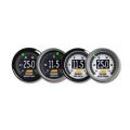
LogWorks Virtual Gauges Showing Air/Fuel Ratio, TPS, MAP, Acceleration, etc.
2 Downloading & Viewing Recorded Data: Innovate makes it easy to pull recorded data down from the LM-1 to your laptop. With your laptop connected to the LM-1, open up the LogWorks Monitor software and click on the "File" drop-down menu, then highlight "Download LM-1 Log" to load your recorded data to your laptop. Once the download completes, you'll see a new window appear with a graphical representation of your session, similar to the screen shot below. You can toggle between multiple sessions using the "Session" drop-down menu of that new chart.

Screen Capture of new LogWorks session chart- Air/Fuel, RPM, MAP, Accel 1.jpg
It's a good habit to immediately save this newly downloaded data onto your laptop before you clear out the LM-1's memory storage of its old sessions. First click on "File" in that newly created graph's window, and then click on "Save As." Type a filename that includes something memorable about the session. An example is "1ClickLessFuel2000_2500RPM_AllMAPs.log" to denote taking one unit of fuel out from 2K-2.5K at all load levels. This practice helps you make sense of the log when you revisit it 3 months later. You can then clear out the LM-1's memory by going back to the LogWorks Monitor and clicking "File" and then "Reset LM-1 Log."
3 Baseline Practices: One of the first things tuners do before altering a fuel curve on any EFI car is to make a copy of the existing EFI system's map – assuming that the system allows you to copy the file to your laptop and later upload that file back into the ECU. This is helpful when you want to undo a change you've made to the fuel map. Now is also a good time to capture some baseline data about how the car runs before you make any adjustments to the original fuel map. Drive the car, record the data and download the data (and ECU fuel map file if possible) to your laptop – before making any changes. Then analyze the data, make your adjustments and drive the car again to determine if your changes resulted in the desired effect.
A good, safe practice is to baseline (and data log) a few runs on the dyno before making any changes to the fuel map (or spark map for that matter). With your baseline captured, you can compare your baseline run data against subsequent run data (done after adjustments).
4 Idle Tuning : Compared to the effort required to tune a carbureted car's idle circuit (which does double duty as the cruise circuit), tuning EFI systems for idle & cruise with a wideband is very simple. Most EFI systems apply the axes of RPM and Load ( MAP value) in order to arrive at an amount of fuel to inject. In the following diagram of an EFI system's fuel map, Engine RPM is the horizontal X axis and Load (MAP value) is the vertical Y axis. The numbers in each X-Y cell tell the EFI system how long to hold a fuel injector open for that RPM and MAP value.

EFI Fuel Mapping
For an example, say that you've captured some data and are reviewing it in the LogWorks interface shown in the following diagram. You click on LogWorks's gauge-like button in the upper left hand corner of the window, just below the drop-down menu for "Channels" to allow you to add a metrics box that shows the values of the data collected at that point in time. You can add as many metrics boxes as you like, and you can remove them just as easily by clicking on them again. The graph shows that at a 900 RPM idle the Air/Fuel Ratio is 13.5:1.

Idle Tune Air/Fuel Graph
If you want to lean it out just a tad (EFI guys are such perfectionists..) just open your EFI system's interface and make a few changes. With the interface open, locate the 900 RPM range for -12 to -10 PSI of MAP or Vacuum , highlight those cells as shown in the following diagram and then tap the minus key (-) to reduce the amount of fuel administered to your engine at idle. Less sophisticated EFI systems may require you to manually type in the values for these numbers, but even typing still beats the carbureted alternative if twisting mixture screws and replacing idle air bleeds.

Idle Change in ECU Software
Start the car up again and check the LogWorks gauges. The Air/Fuel Ratio has changed to 14.6:1 and the idle is now smoother at 860 RPM with about the same Vacuum . Some EFI interfaces even allow you to make your fuel mapping changes with the engine running, so you have the option of adjusting the fuel map while looking at the LM-1's Air/Fuel Ratio display.
EFI LogWorks Virtual Gauge Dials
Note: Most EFI systems will have a menu option that allows you to trigger an idle compensation system when the car's automatic transmission is in Drive but the car standing still. For those systems that don't, the previous tuning process can be used for cars with an automatic transmission. Remember to chock the wheels, engage the emergency brake and have a friend in the driver's seat pressing the brakes as you tune with the transmission in Drive. You can then sit in the passenger's seat to make the fuel map adjustments using the laptop.
5 Light Cruise Tuning: Next, you can measure and tweak (where necessary) the values in the EFI interface to the right of the cells you just changed. That section (1500 RPM and up, -11 to -12 PSI load ) is used for very light cruise conditions with very little load . Capture your data, make your changes to no more than two horizontal rows at a time, drive the car, capture more data, analyze and repeat as necessary until you feel like your cruise Air/Fuel Ratios are in the range you want them in and you haven't sacrificed drivability or safety. Again, look at your knock voltage readings and compare these against the baseline for any discrepancies. This process allows you to analyze whether your changes resulted in the Air/Fuel Ratios and drivability you sought in that range.
Save the Innovate data captured from the LM-1 (and the EFI system's current file if it allows you to -- using a similar filename convention) under a filename that makes sense to you for the changes you've done. You can at this point begin working your way upward 1 or 2 rows at a time on the EFI system's map to build out the cruise and transition section of the map. That process is described along with a couple of options for tuning the transition section near the end of this discussion.
6 Wide-Open-Throttle (WOT) Tuning: The same level of simplicity applies for tuning the car at wide-open throttle – it's just a different area of the map. Ideally, WOT tuning should be done at a dyno (to measure wheel horsepower and torque) and then the racetrack (compare quarter-mile ET and MPH as well as 60 foot times off the line). Tuning for WOT focuses on the upper part of the EFI system's fuel map shown earlier, where vacuum is closer to -1 or 0 (or positive values for boosted applications) and extends all the way from idle RPM through redline.
Most manufacturers will tune the EFI system to run between 11.5:1 and 12.7:1 in the high load , mid-upper RPM range for optimum power and engine reliability, while running mixtures near 13:1 at slightly lighter loads (-2 PSI). For even lighter loads, the EFI system switches into a "closed loop" feedback system that targets 14.7:1 for optimum fuel economy and emissions.
Looking at the high-load part of the map in the following table, look at the turquoise rows of Air/Fuel Ratio . This map is a LogWorks table taken from a Honda S2000 running on its factory fuel map. The table consists of many sessions collected across a wide range of throttle, RPM and load conditions.

Baseline Table
At the 0 and -1 PSI range (Wide Open Throttle), the Air/Fuel Ratio is between 11.8:1 and 12:1 from 1500 RPM up to 8250 RPM. However, the Air/Fuel Ratio seems to drop after 8250 RPM down into the 10:1 range – not conducive to maximum power. This is where Innovate's data logging can find you some horsepower by highlighting an opportunity to raise the Air/Fuel Ratio back into the 11s from 8250 to redline. The pink Air/Fuel Ratio line in the corresponding dyno run from this Honda confirms that the engine goes too rich after 8250 – the pink Air/Fuel Ratio line drops over a full point of Air/Fuel Ratio from 7500 RPM to 8500 RPM.

Baseline AFR Example
What's happening is that Honda deliberately adds extra fuel after 8400 RPM (the stock S2000's power peak) to drop the Air/Fuel Ratio down into the 10s. This artificially limits the power peak to 8400 RPM instead of the engine's true peak flow potential at 8800 RPM – where 8-12 more horsepower is available. Honda does this to reduce the likelihood of an average owner bumping into the fuel cutoff at 8900 RPM. Aftermarket "black boxes" like those from Greddy and Apex can run on top of the factory ECU, allowing an experienced tuner to use a wideband system like Innovate's LM-1 and tap that extra 12 horsepower by trimming the excess fuel injected between 8400 RPM and redline. This can be done by plugging your laptop into the black box's interface and editing the relevant RPM/ Load cells in a fuel map screen that's similar to what was described earlier in the Idle section. If you instead have a "stand-alone" aftermarket ECU in place of the factory ECU (as in the following diagram), you simply open up the interface and make your changes to the RPM/ Load cells there, and then go back and test for the resulting changes.

WOT Fuel Trim
It's safest to do this type of fine-tuning on a dyno first, paying careful attention to the Innovate LM-1's Air/Fuel Ratio readout and data logs in the areas of RPM and Load where you made the changes. In addition, pay close attention to the knock voltage you're logging in the LMA-3 and viewing in LogWorks. Compare your baseline logs against each set of changes so you can avoid harmful detonation.
7 Transition Tuning: You've now used your Innovate LM-1, LMA-3 and LogWorks software to check for knock and to fine-tune the idle and wide-open-throttle ranges of your car's EFI fuel map. All that's left is to "fill in the blanks" between idle and wide-open-throttle in the EFI system's fuel map. One of the easiest ways to measure and refine your EFI fuel maps in this "transition" area is to take your car to a dyno shop and make many dyno pulls, being sure to capture the data with your Innovate equipment. Although you may need to rent a few hours to thoroughly tackle all the ranges, a couple of hundred dollars is far less expensive than replacing an engine.
Concentrate on one load range at a time and use the Innovate LogWorks Instrument Panel of configurable dials to make each pull. Remember to hit "Record" on the LM-1 before you start this process. One approach is to base your pulls on TPS , making a full pull (from 1500 RPM or so up to redline or until the RPM plateaus) using only 10% throttle. You will have to actively watch the TPS dial and control your foot to ensure you keep it at 10% for the full pull. Then make another pull, this time at 20%, then 30% and so on until you make your last pull at 100% throttle.
Next, you can try capturing data based on making pulls referenced by engine load – trying to keep engine load ( MAP value or Vacuum ) as constant as possible through the pull or until the engine plateaus at an RPM level, starting at a load level that is a row or two above the idle load level you've set in the EFI system's fuel map. This practice is infrequently done, but can provide insight into stumbles or hiccups that aren't otherwise only show up in normal street driving.
After your final pull (of TPS and Load/MAP), download the data you recorded from the LM-1 to your laptop. Open up LogWorks's "View" drop-down menu, then click on "New Chart" option to bring up the Chart Settings box like the following graphic:

Viewing New Chart
Set your Horizontal axis to RPM and your Vertical axis to MAP and your Chart Content as LM1_O2 and click OK to bring up the table. Next, click on "Sessions" to select all of your sessions as content for the table you're building – this allows you to capture all the Air/Fuel Ratio s for the various dyno pulls you just ran and display them as a single table which you can very easily color code for easier viewing.
Enable color-coding by clicking on "Colors" and selecting the color scheme of your preference. Cells in the table automatically become color coded based on their numerical value. The color scheme in the following diagram is "Wobniar" (which is "Rainbow" spelled backwards) and intuitively has blue at the rich / cool side of the Air/Fuel Ratio spectrum and red as the lean / hot side.

EFI Transitions Viewed as Color-coded Table
Review the LogWorks table to examine cells that contain Air/Fuel Ratio s that don't make sense for the area of the fuel map that they are in. The previous table has a red cell in the lower right corner with a dangerously lean 22.39 Air/Fuel Ratio at 8500 RPM and 8.3 pounds of boost (this table is from an EFI car with a small turbo). The EFI system's fuel map needs to be checked and likely richened in that range. It also appears that there are some lean cells (over 15:1 Air/Fuel Ratio ) within the 4500 RPM – 5000 RPM range between -12 PSI and -3.18 PSI which need to have fuel added as well.
Remember to make one change at a time, measure the results, and repeat. Soon you will be "finding" horsepower and efficiency in all sorts of unexpected places!
Standalone ECU Tuning
Most modern standalone Engine Control Units can benefit from the use of a wideband Air/Fuel meter.A few of the basic applications are closed-loop EFI operation, tuning and setup, and narrow-band emulation.
Closed-loop EFI operation.In this application, the wideband controller (LM-1, etc.) controls the wideband oxygen sensor, and outputs a 0-5V signal that continuously informs the ECU what the measured air/fuel ratio is. The trick is to match the voltage-to-AFR correlation so that it is mapped correctly to the ECU. All Innovate wideband controllers have programmable analog outputs, so often it is as simple as determining what the ECU is "looking for," and programming the LM-1 to match it. Innovate digital wideband outputs are truly linear, and many older analog controllers are non-linear, so, in some cases, you'll need to reprogram the ECU's input table to match the Innovate output. Here's an example from a Electromotive Tech-3 ECU (link to Tech-3 App. Note):

Remember to ground the analog output to the same ground as the ECU to avoid ground offset issues. If you still see ground offset, you can shift the LC-1 or LM-1's output to compensate. NOTE: Some ECUs will operate in closed-loop mode only at cruise or idle (not at WOT), so check the specs on your ECU.
Basic Tuning. Another common application of tuning a standalone ECU involves utilizing Innovate datalogging capabilities (LM-1, DL-32, or LogWorks direct on a PC). Most ECUs ship with a base fuel map. This map is designed to get the vehicle running safely so that it can then be tuned to optimum. Accordingly, the base map is almost always far from perfect. Often it is way to rich, which means you're wasting fuel and losing horsepower.
The process here is to record a log of AFR and RPM (at least). With LogWorks, you can then graph and chart the actual AFRs, under real road conditions, at every load and RPM. With a chart like this:

You can make appropriate changes to your ECU's target fuel map, then repeat the process. By logging other key variables, such as throttle position- TPS, manifold absolute pressure- MAP, cylinder head temperature-CHT, and/or acceleration, you can further understand exactly what's going on with your engine, and dial in it in for maximum power, maximum efficiency, or the perfect balance.
Narrow-band emulation. In some cases, your ECU might operate best with a narrow-band oxygen sensor input. You can use the LM-1 to provide this also. The factory setting for output #1 is set to emulate the steep and narrow output curve of a stock narrow-band sensor. You can also shift this to "trick" an ECU into providing more horsepower under some conditions.
Piggy-back Fuel Controllers
Piggy-back fuel controllers are popular because they allow users to modify stock fuel injection without replacing the entire ECU. They operate in various ways. Some of them modify the injector duty cycle control signals as they travel from the ECU to the injectors. Others modify input data to the ECU (like MAF for example), effectively "tricking" the ECU into delivering more or less fuel at a given RPM. Regardless of how exactly the piggy-back works, you'll want to measure the results of any modifications you make to your fueling map.
Even if you can't tune the piggy-back (some are fixed and not user programmable), you'll want to make a log before and after you add the piggy-back. This helps you evaluate what exactly it's trying to do, and avoid dangerous lean conditions or wastefully rich conditions. If you can tune your piggy-back, use the LM-1 to carefully tune every cell of your fuel map.
Laptop Tuning
A new wave of laptop tuning tools have been coming to market that allow users to directly modify the fuel and timing maps of stock ECUs. These usually use the OBD-II port (On Board Diagnostics). Some of them, such as the EcuTEK system for Subaru WRXs, can directly read the LM-1's digital data stream and display AFR or lambda in the EcuTEK software. For all of them, you'll want to be carefully measuring air/fuel ratios (and other variables) while you're tuning.

Chip Tuning and Re-Flashing Devices
Handheld chip re-flashers have been around for a while. But recently, many of the most popular units are adding features that allow users to change key parameters like fueling curves and ignition timing.
The basic scenario is always the same: Use your LM-2 to log AFR, RPM, MAP, etc. before and after each change.
Squirt and Spark: How your ECU Works
There's a photo of me as a six-year old in my family's driveway. The look on my face is one of extreme concentration – I have a stethoscope in my ears and I'm hunched over the V12 that lived (and died) under the hood of my father's Jaguar. He is beside me, instructing me on how to adjust the four Zenith carburetors for balance by listening to the subtle changes in pitch at the air intake of each one. Didn't make the thing any more reliable, of course. But it made you feel you'd done something anyway.
Over the last 26 years I've figured out how most of an automobile works, and even got good enough at balancing the SUs on my own various MGs and early Jags that I can take care of it while my girlfriend pops into the loo at the filling station, which is about how often you have to do it
But then they went and invented fuel injection, and then engine management that unites fuel injection with engine ignition, and then they went and packed it in a little metal box. All the magic little set screws and plungers and orifices and weighted distributor advances and points gaps are set into a microchip, and you can hardly tell which part to hold the stethoscope to.
Unless you're one of the few who really understand how a modern Electronic Control Unit (ECU) works, it is probable that you subscribe to Arthur C. Clarke's notion that "any sufficiently advanced technology is indistinguishable from magic." If so, read on.
The Computers Are Just Smarter
Modern engine management is not rocket science. Its just doing the same thing that carburetors and distributors used to do, but better. We know (and the computer is programmed with) the ideal amount of fuel to mix with a certain amount of air at various engine speed and load levels. In The Olden Days the venturis and jets in your carburetor used to approximate this.
We and the computer also know when the plugs should spark to ignite this mixture for best burning at different speeds and loads. All of this was previously the job of your distributor and some kind of advance mechanism, and again it was approximated. Looking at how approximate the ignition and mixture used to be, it's remarkable that old cars ran at all. Certainly they ran very inefficiently.
Now, thanks to ECUs, we are in a halcyon era of powerful engines with flexible powerbands and relatively low emissions and high fuel efficiency. That Jag of my father's was the fastest sedan in the world when it was introduced. It put out 250hp from a 5.3 liter V12. Now you have 250hp in a 2005 Subaru Legacy with a 2.5 liter 4-banger. Internal combustion hasn't changed; the computers have taken over.
It's All About the Sensors
Electronic engine management is all about getting accurate information from the engine's environment and then sending out accurate signals to the control mechanisms of the engine. In a typical system you have the following input sensors:
1. throttle position of the accelerator
2. air temperature in the intake manifold
3. air pressure (or weight of the air) in the intake manifold
4. a measure of the residual oxygen in the exhaust manifold (the O2 sensor)
5. engine rpm
6. camshaft position
7. crankshaft position
8. engine load, usually as a function of manifold vacuum pressure
9. engine coolant temperature
10. about a zillion other things, like "knock" sensing, battery voltage, ambient air temperature, and whether Hoobastank is still on the Billboard top 40.
The computer simply takes all this data, compares it to data about optimum spark and fuel volumes for different conditions, and controls how much fuel to inject and when to fire the spark plugs.
Modern Mixture and Maps:
We know that there is an ideal air:fuel mixture ratio for each type of fuel - for gasoline this is 14.7 weight units of air to 1 weight unit of fuel, a so-called "stoichiometric" mixture. In principle, this is the mixture point at which all fuel injected will combust with all the gases in the ambient air. However the combustion is rarely perfect – an oxygen may never meet a hydrocarbon on the other side of a crowded cylinder of dancing vapours - so a somewhat leaner mixture (around 16:1) will ensure that excess air will gather up all of the hydrocarbons in the fuel and so will produce fewer emissions and better fuel efficiency. On the other hand a richer mixture will ensure that all the air that can be moved into the engine will combine with hydrocarbons in the fuel and so for maximum power you actually want this mixture to be richer - closer to 12:1. Since you're more concerned with power under hard acceleration and less concerned on the overrun (when you lift the throttle), the computer can target leaner and richer mixture ratios depending, literally, on how hard you stomp on the throttle.
Maintaining the ideal mixture is the function of your "fuel map" and it determines how much fuel the ECU will inject during each cycle of the engine. Essentially the map is a compromise to give you power when you want it, keep emissions as low as possible, and all the time keep the mixture within safe parameters to avoid damage to the engine.
How much Air?
Before it can determine how much fuel to squirt in, the main challenge for the ECU is to know what weight of air is in the intake manifold and getting sucked (normally aspirated) or pushed (turbo or supercharged) through the intake valve. Modern ECUs measure this in one of two ways: either by taking the pressure and temperature of the air in the manifold and calculating Manifold Absolute Pressure (MAP), or by measuring the weight of the air (Mass Air Flow or MAF) as it moves into the intake past a heated wire filament across which the ECU can measure electrical resistance. Older systems used other means, including various flaps and pulleys (I'm not kidding) to measure airflow. Now most production cars use MAF, although I use MAP in my rally car and some manufacturers, including Subaru, are moving back towards this.
How Much Fuel?
The main mixture job of the ECU is to control the injectors. Fuel injectors are little spray nozzles that can be snapped open and shut by an electrical charge: the amount of time they're open, combined with the pressure of the fuel coming in and the size of the injector, determines how much fuel will be injected. In "multi-point" fuel injection systems there's an injector for each cylinder, while in more basic systems ("Throttle Body Injection") there's just one for the whole intake.
So what determines how long the injectors stay open? The ECU senses the weight of the air, the rpm of the engine, and compares this to the data "map" it contains about ideal mixture for each load-rpm condition (see "base fuel delivery" graph). It then decides how long to open the injectors for and sends an electrical signal to them for the right amount of time. At idle the injectors open for just a millisecond – long enough to keep the engine ticking and no more. But mash the throttle and they go towards the maximum "duty cycle" – theoretically they could stay open 100% of the time but generally are engineered to give full throttle by being open about 80% of the time – that is, 80% of the time that it takes the crankshaft to go around twice. Thus is mixture in the modern engine determined.
When to Spark?
As engine speed increases, you need to ignite the mixture in the combustion chamber progressively earlier to get most efficient ignition. Note that the "explosion" in each cylinder is really a very fast fire and that the "fire front" moves through the mixture until burning is complete. The earlier you can spark the mixture, the more power you'll get as there will be more time to burn all the vapour before the exhaust valve opens. But if you fire the spark too early, you will end up with the explosion completing too soon and you get an uneven leading edge to the burn – effectively a separate explosion - called a "detonation." This may allow a "hot spot" of the explosion to hit the top of the piston (normally it is protected by a barrier of other gases at the edge of the explosion), and this is what a "knock" in the engine is. All engines knock somewhat, actually, but if you don't keep it within an acceptable level you will burn a hole right through the piston. Don't ask me how I know.
Higher octane fuel, by the way, burns more consistently at the leading edge, which is why for most race applications we use fuels with an octane above 100 while you might use 87 in your street car, and why we can advance the timing and run higher compression in the race cars. Lead additives in the fuel prevent detonation, but as you know this is mildly toxic and so we don't use it any more. Of course blowing engines is mildly toxic, too.
So for ignition, you have a second "map" that determines when to fire the spark plugs, based again on engine rpm and load (see "base ignition timing" map). In many four cylinder engines you have two coil packs and each has two plugs attached to it – when the ECU determines it's the right time to fire one of the plugs it sends current to one of the coil packs and two plugs actually fire, although one is redundant and has no fuel to ignite (creating a "waste spark"). It's just cheaper and more reliable than having four individual coils or (horror!) a distributor.
Other Stuff:
So the fuel delivery and spark timing maps are the real essence of what the ECU is doing for you all the time. Thousands of times per second the ECU is calculating how much fuel to deliver and when to spark.
But that's not all. For example, it knows when the engine is cold and it delivers more fuel and adjusts the spark for smooth running until the engine warms up. It also knows if the engine gets too hot and it can drop into "limp mode" to get you home by cooling the explosions with a richer mixture and later spark.
It also has two other very important sensors that adjust the fuel and spark maps constantly. The first is the "oxygen sensor" in the exhaust manifold, which sends information about how much oxygen is left over after the explosions in the engine. The computer takes this data and constantly adjusts the fuel mixture to keep this near maximum efficiency (14.7:1) or maximum power (12:1) depending on settings. Running in this mode is known as "closed loop" as the ECU is constantly adjusting itself to get the desired exhaust. There are a couple of interesting consequences to this: it self-adjusts for different qualities of fuel, and (this is cool) it even learns to change the entire fuel map for the car as the engine wears over the life of the car. But the sensor itself is a rather specialized device and deteriorates over time, which is why the #1 emissions-test failure is a faulty oxygen sensor. Now you know.
The second common and important feedback sensor is a little microphone attached to the engine block that can sense "knocking" or detonation from the cylinders, allowing the computer to adjust the timing backward (later) to prevent damage to the pistons. A few knocks per 100 cycles will be OK. More is bad. Note that there can be problems associated with this sensor: the Mitsubishi 4G63 engines especially in Galant VR4s and Talons can be afflicted with a "phantom knock" even when the engine is running properly but goes into limp mode anyway, sapping power. Basically the microphone is picking up noise from somewhere else in the engine and sending it to the computer as a knock; many Mitsu people find that the valve lifters are the source of the noise. Similarly, in a rally car we have constant barrage of noise from rocks on the chassis and this can be picked up. As a result, I don't have a knock sensor.
Opening Pandora's Box:
So now you have a dangerous amount of knowledge and want to completely remap your Honda, right? Be careful. It's not rocket science, but it's not model rocketry either. Still, there is good reason to start fooling around. Modern cars are mapped to provide a reasonable tradeoff between fuel efficiency, emissions, and power. If you care more about one of these things you can tune the engine more aggressively towards that. I'm going out on a limb and guessing you want more power, right?
Basically your typical aftermarket remapping is about richening the mixture throughout the range towards maximum power (12:1) and away from maximum efficiency (14.7:1). You'll use more fuel, but get more grins. Also you'll get more emissions, not just because of the residual hydrocarbons in the exhaust, but because this will cool the exhaust and catalytic converters are designed to operate within a very narrow temperature window.
In terms of timing, the factory settings are very conservative, presuming you will run rotten fuel sometimes and that you want the engine to last for a while. If you're committed to running higher-octane fuel all the time and putting your engine at some risk of detonation, then you can advance the timing a bit and get more power.
How much more power, and how to get it?
Basically you have four options if you start playing with your ECU: 1. replace or "reflash" the memory chip that contains your fuel and timing maps. Normally you remove the ECU and send it away for this to be done; some devices now exist for you to do this on your own. ($50 to $800) 2. Put a "piggyback" additional board between the ECU and the sensors/injectors/coils that modifies the signals to and fro and allows you to effectively remap the engine, although you're limited by some of the original ECU's parameters. ($500 to $1200). Note that you can reflash the chip at the same time to open the limiting parameters, and I've seen 450hp Evos with this system. 3. Replace the entire board in your original ECU case and plug the factory wiring harness directly into it (a "plug-and-play" board) that offers full programmability. This is what I use in my rally car. (to approx. $2000) Or 4. replace the ECU with an aftermarket one that will require you to significantly rewire your car (to approx. $2000).
But the real challenge is not how to get programmability. It's what to program. Either you should rely on another tuner's wisdom and use their maps (Dinan, Cobb, Vishnu, etc.), or you need to get on a dyno and burn up some tanks of fuel to find out what mixtures and timings really produce the most power and torque for your particular engine on your particular fuel. It's a time-consuming and precision process and requires some experience. The bottom line is what you see on the horsepower and torque curves from the dyno.
There's another device you need, though, and I'm happy to report that it is now available to the common man. You need to get information from that oxygen sensor in the exhaust so that you can monitor mixture while you're tuning for power – too lean and you'll start blowing engines; too rich and you'll lose power (and, at the extreme, start blowing engines). Although you can get little LED readouts for your dash that appear to tell you about mixture they're not accurate enough and you really need a digital device that can log the mixture against load, rpm, throttle position, etc. Until recently, the main options were air-fuel meters available from MoTEC ($2200US) or Autronic ($1800US) which is a serious investment.
But there's a new product on the market that I've used and I love: Innovate Motorsports (www.innovatemotorsports.com) now makes an affordable fully digital and data-logging air-fuel meter that retails for $349US. I've used it to tune my Evo already and I find it perfect for the job. Install the sensor in your exhaust and power the device up and you are already looking at the A/F ratio (or "lambda"). Wire in up to five additional inputs and you can watch them on screen as you tune, or log them for up to 44 minutes in the device itself and download it later (great for road tests). Also you can take the analog output signal and feed it to your ECU, as I've done, so that you can see A/F ratio against all the other engine parameters you can monitor by hooking up directly to the ECU. I really like this device, and won't tune without it now. I recommend it strongly. It won the SEMA award for "Best New Product – Performance and Racing" this spring and I can see why.
Conclusions:
The bottom line is this: ECUs use a group of sensors to gather information about engine running conditions and use two maps – one for fuel and one for spark – to control how long to open the injectors and when to fire the spark. Playing with these yourself is entirely possible, although it requires some knowledge to get the best out of it. Note that any remapping is likely to cause you to fail emissions tests and void the warranty of your car, so you've been warned. But who's thinking about that when you're putting out 450hp from 2 liters, right? Best of all: no stethoscope required.
Recommended Reading: Forbes Aird, Bosch Fuel Injection Systems, HP Books 2001.