














APR Intercooler System for Audi B9 1.8/2.0 TFSI
Das APR -Ladeluftkühlersystem ist ein massives Front -Mount -Upgrade, das die Ansaugtemperatur (IAT) dramatisch reduziert, das Wärme einweichen und die Leistung erhöht! Das System ist einfach zu installieren, direktes Bolzen-On-Design, das in jeder Leistungsphase empfohlen wird.
Funktionen
- Dramatisch senkt Ansauglufttemperatur (IAT)
Erhöht die PS, während die Leistungseinbußen durch Hitzeeinwirkung minimiert werden!
Behalten so hoch wie 45 AWHP im Vergleich zum Werkssystem! - Massive frontale Oberfläche und Kernvolumen
3.125" x 5.75" x 28.25" - 162.4 in² frnt. & 507.62 in³ volume - OEM
2.250" x 16.2" x 22.00" - 356.4 in² frnt. & 801.90 in³ volume - APR - Hochwirksames Kern-Design
Bar-und-Plattenkern mit versetzten und gelochten Flossen.
Rigorose Tests haben den Kernstil, die Flossen-Dichte und die Größe bestimmt.
Geringer Druckverlust + hochwirksame Kühlung = hohe Leistung! - Glatte Guss-Endtanks
Entwickelt für geringe Turbulenzen/Einschränkungen und maximalen Durchfluss.
Organically shaped to promote airflow across entire core.
Druck getestet, um leistungsraubende Ladedruckverluste zu verhindern. - Silikon Einlass- und Auslassschläuche
Mehrschichtiges Silikondesign mit interner Drahtverstärkung, fluorosilikoner interner Schutzschicht und APR's EZ-Flow gestuftem Design. - Clampco T-Bolzenklemmen
Starke, rostfreie Clampco T-Bolt-Klemmen bieten eine bessere Klemmkraft für erhöhten Schutz gegen Schlauchrutschen und Leistungsverluste. - Billet MAP Gehäuse
Präzisions-CNC-bearbeitet für sichere Sensorplatzierung mit attraktiver matt-schwarzer eloxierter Oberfläche. - Einfach zu installieren
Einfache Anbringung ohne zuschneiden oder bohren erforderlich! - Designed by engineers with lasers
Mit der besten Ausrüstung und den klügsten Ingenieuren funktioniert es einfach!
Design
Unfortunately, to the untrained eye, many intercooler designs appear the same. However, effectiveness of the system and overall performance are greatly determined by several key metrics. Alloy selection, end tank design, construction type, fin style, fin density and overall core dimensions must be analyzed and balanced accordingly to deliver class-leading performance. While the OEM’s goal is to create a lightweight, easy to manufacture and inexpensive to produce, cross-platform design capable of supporting factory power levels, APR’s intercooler must be capable of supporting more than double the factory output. Achieving this goal took a multi-step approach focused around intercooler core selection, end tank design and install location.
Intercooler Core Design
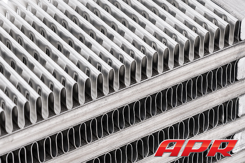
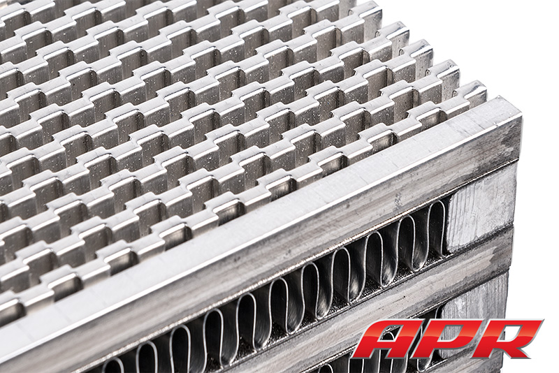
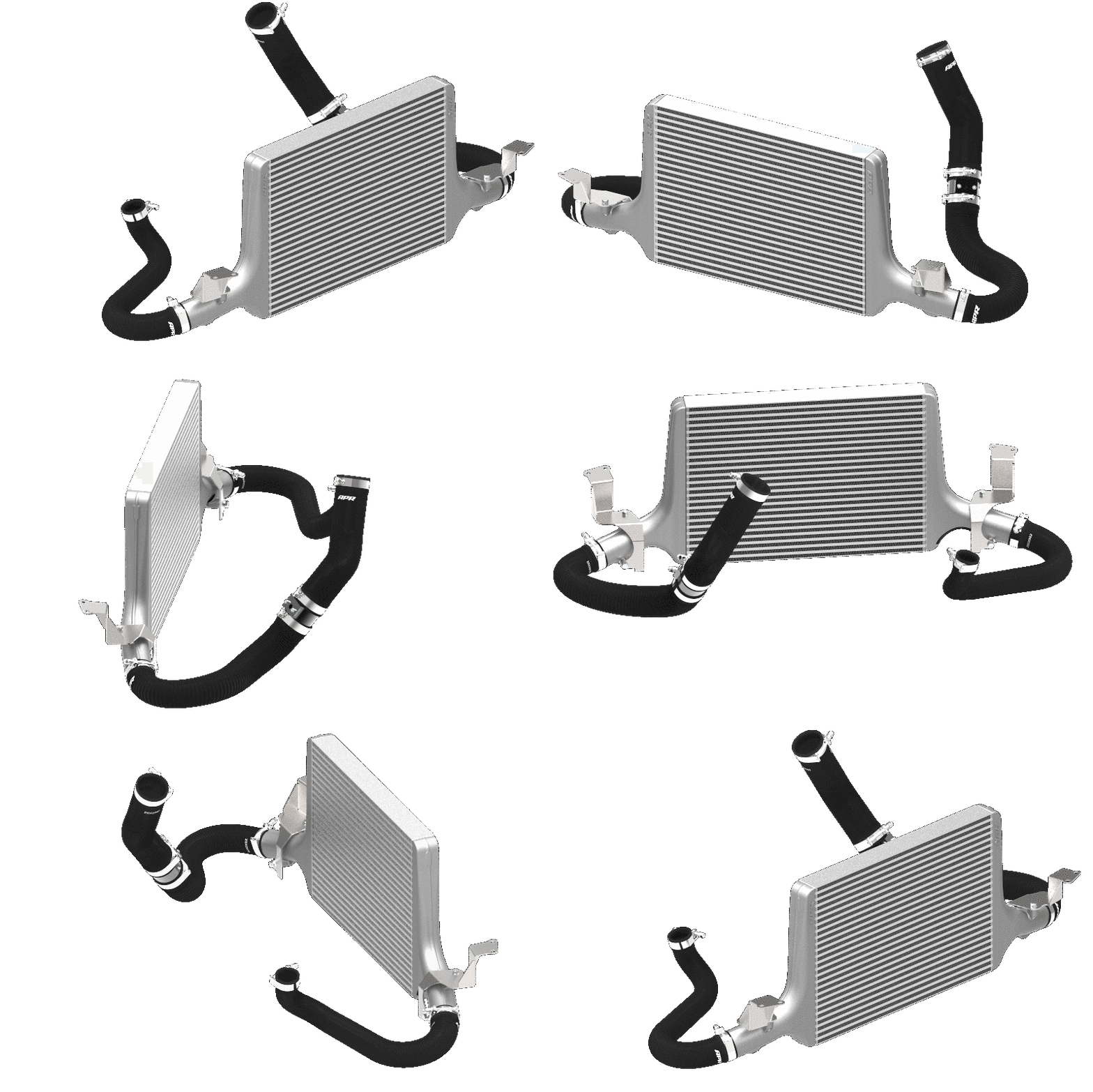
The APR Intercooler core is a large bar-and-plate design featuring densely packed staggered and louvered fins. This design offers exceptional cooling while balancing pressure loss across the core, and maintaining critical airflow to the components behind the intercooler system. The core size was appropriately matched to the platform, minimizing pressure drop while leaving adequate space for appropriately designed end tanks. To APR’s mechanical engineering experts, the design represented the ultimate in performance, far exceeding the capabilities of the factory intercooler. To the driver, the result is simple: Repeatable performance, even in the most demanding of situations!
Core Style / Internal Fin Structure:
APR’s Engineers paid close attention to the balance between core effectiveness and pressure drop through the core, core style and fin density. With fin density too low, pressure drop decreases dramatically, but typically results in a core incapable of effectively cooling. Likewise, with fin density too great, pressure drop increases dramatically, resulting in the turbocharger working harder, and hotter, to produce the same level of airflow. By fine tuning this often unseen balancing act, as illustrated below, APR’s Engineers were able to maximize performance.
| System | Core Type | Thickness | Width | Height | Volume | Frontal Area |
|---|---|---|---|---|---|---|
| OEM | Tube and Fin | 3.125" | 28.25" | 5.75" | 507.62 in³ | 162.4 in² |
| APR | Bar and Plate | 2.25" | 22" | 16.2" | 801.9 in³ | 356.45 in² |
The APR system increases frontal surface area by 119.09% and has a 58% larger core!
Intercooler End Tank Design
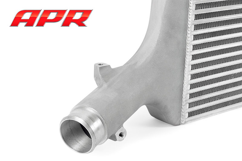
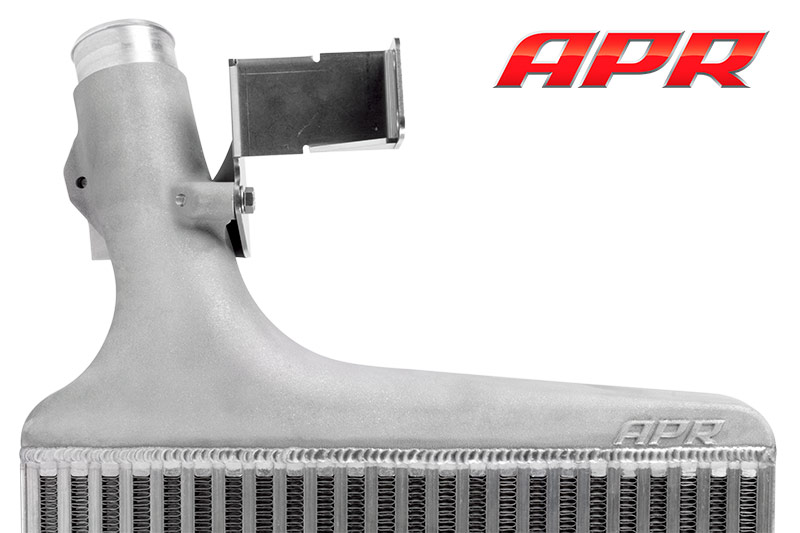
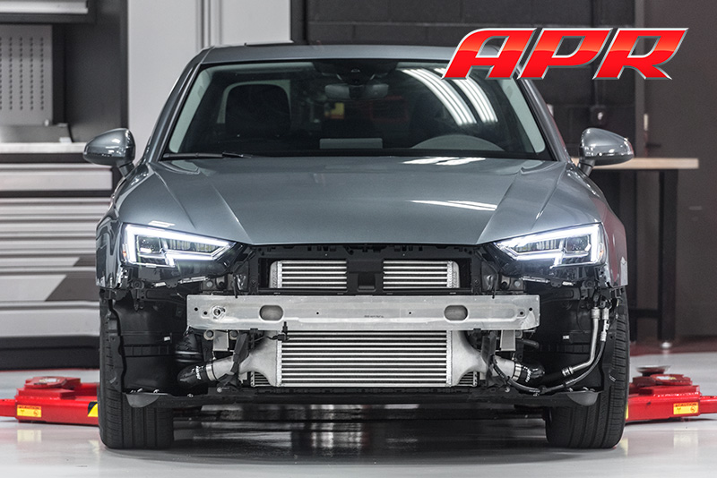
To fully utilize the massive core, APR’s mechanical engineers designed cast aluminum end tanks organically shaped for proper airflow distribution across the entire core. By correctly sizing the intercooler core, end tank design was not sacrificed. The one-piece end tanks are CNC machined to provide a slip resistant mounting surface for hoses, precise integrated mounting surfaces, and perfectly flat connecting surfaces used for TIG welding the tanks to the core. Through proper alignment in welding jigs, each unit is assembled to tight tolerances for a precise and accurate fit.
Intercooler Bracket Design
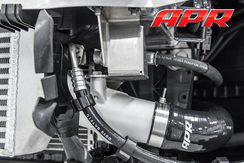
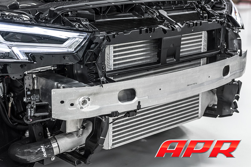
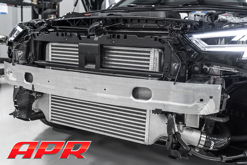
APR’s mechanical engineers designed CNC-bent and TIG-welded mounting brackets to securely hold the intercooler in place. The brackets make the install extremely easy. With the bumper and factory intercooler unit removed, the APR intercooler installs in minutes without any cutting, drilling or trimming. For the DIY customer, this makes a home install simple, and for everyone else it eliminates hidden costs that often come with a more labor intensive install.
Intercooler Hoses and Clamps
The APR Intercooler System includes the highest quality silicone inlet and outlet hoses, T-bolt clamps and billet MAP housing. Each component is designed to protect against boost leaks at extreme pressures, and stand the test of time.
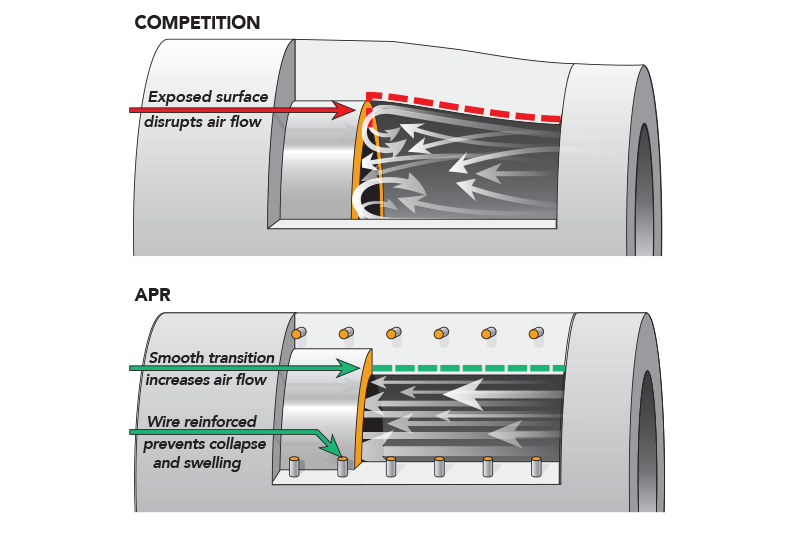
Hoses: The hoses are constructed from multi-ply silicone, and are wire-reinforced to prevent swelling and bursting at extreme boost pressures. Internally, the hoses are lined with fluorosilicone to protect the hoses from oil and gasoline deterioration. Finally, each hose feature’s APR’s EZ-Flow stepped design to provide a smooth airflow path at the hose transition points.
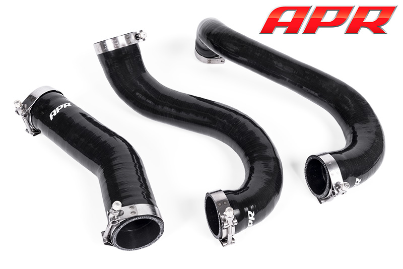
Clamps: Strong Clampco T-bolt clamps are used throughout, replacing the factory worm-gear clamps. The clamps are made from stainless steel, and are of a high-quality and high-strength design that diminishes the risk of boost leaks. Lastly, the clamp’s thick clamping style provides increased connection strength, and decreased hose slippage compared to other styles of clamps.
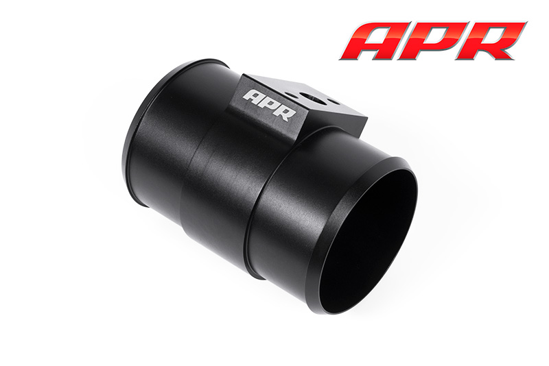
MAP Housing: A billet MAP sensor housing provides a secure mounting point for the factory pre-throttle MAP sensor. The precision cnc-machined housing helps to prevent leaks around the sensor, and the matte-black anodizing gives the housing a clean and attractive look within the engine bay.
Testing
APR’s engineers conducted a multitude of tests both on the street and on the dyno with thermocouples and pressure transducers placed at the inlet and outlet of the intercooler during the design phase. Data from these tests were used to choose the intercooler core available today. With the intercooler in its final production form, tests were conducted against the factory intercooler to measure the effectiveness of each system.
Testing conducted on the dyno provided a semi controlled environment for back-to-back stress testing the two systems. Utilizing a B9 A4 2.0T at APR Stage I power levels with 100 octanes in the tank to prevent timing pull associated with higher intake air temperature seen with the stock intercooler, six back-to-back dyno pulls were conducted with minimal cooldown time between runs. APR’s ECU Explorer high resolution datalogging system was used for raw sensor data collection.
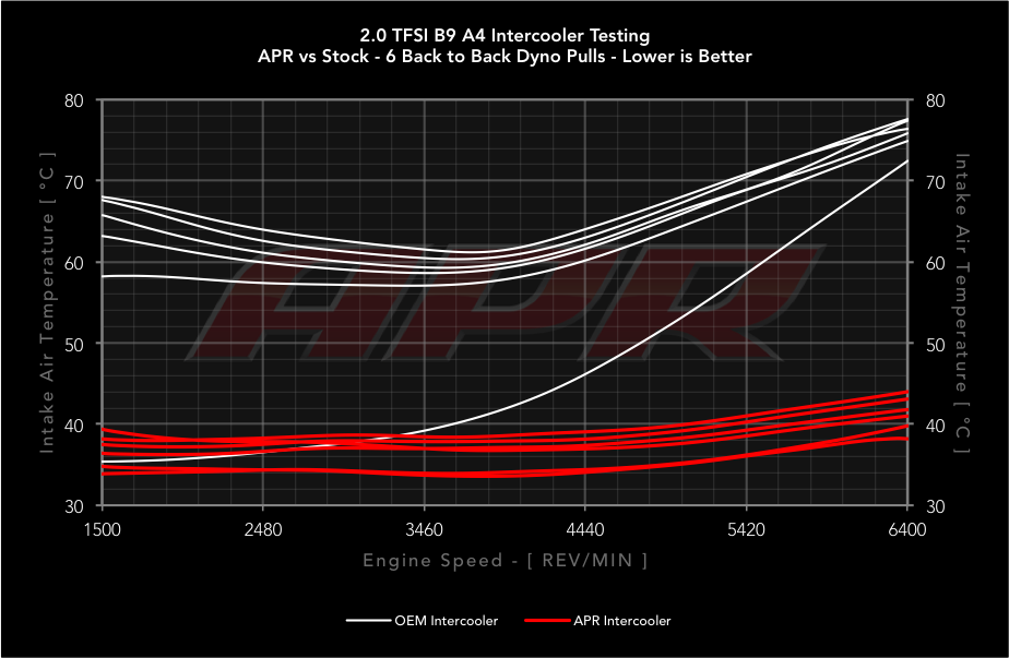
The APR intercooler saw a beginning IAT of 33.90°C that rose slightly to 38.20°C by the end of the first dyno pull. IAT remained consistent during the six back-to-back pulls, resulting in a final IAT of only 44.00°C! The system effectively rejected heat soak and produced consistent horsepower results stacking evenly on top of each previous run.
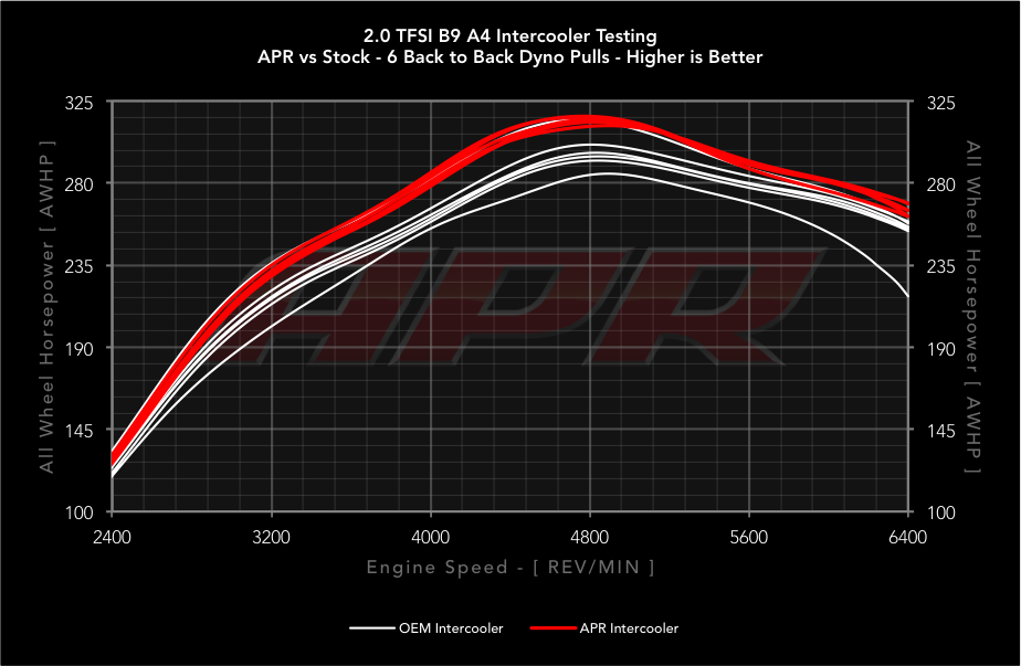
The OEM intercooler did not fare so well. With a starting IAT of 33.40°C, IAT skyrocketed during the first pull, settling at a blazing 72.45°C, or 34.25°C higher than the APR Intercooler. IAT continued to climb during the six back-to-back pulls, resulting in a final IAT of 77.8°C. With each new pull, horsepower dropped considerably, ultimately resulting in horsepower figures as low as 45 AWHP less than those captured with the APR intercooler!
| Start | Run 1 | Run 2 | Run 3 | Run 4 | Run 5 | Run 6 | |
|---|---|---|---|---|---|---|---|
| OEM | 35.40 °C | 72.45 °C | 74.90 °C | 75.85 °C | 76.40 °C | 77.74 °C | 77.8 °C |
| APR | 33.90 °C | 38.20 °C | 39.80 °C | 41.00 °C | 41.80 °C | 43.10 °C | 44.00 °C |
| Delta | -1.50 °C | -34.25 °C | -35.10 °C | -34.85 °C | -34.60 °C | -34.30 °C | -33.80 °C |